
Machine Learning based Obstacle Avoider
04 Dec 2015Introduction
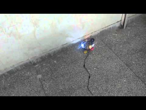
This project aims at developing an Artificial Neural Network controlled autonomous robot which can avoid any kind of obstacles in its path. I have used Firebird V robot developed by Nexus Robotics for demonstration. A webcam is mounted on top of robot which is further connected to a laptop. Image captured by webcam will be processed on laptop using a python script. After processing, these images will be fed to the trained Neural network which will control the navigation of robot. The output of ANN is wirelessly transmitted to robot using XBee module. For this project I have referred Robot Navigation Control Based on Monocular Images journal by William Benn and Stanislao Lauria.
Tools
OpenCV 2.4, an Open-source Computer Vision library is used with Python 2.7. For instructions regarding the installation of OpenCV refer documentation.
Algorithm
The algorithm is divided into two major parts:
- Image Processing
- Machine Learning
Image Processing
The images taken by camera can’t be directly fed to an ANN for training. They have to be converted to a suitable format for training. In order to identify obstacles a two step process of Colour Image Segmentation and Edge Detection has been implemented. Once the image has been processed in this way, fuzzy logic, neural networks, and so forth could then be considered to optimise decisions and control the robot navigation strategies.
- Image Colour Segmentation
For robot navigation, image segmentation is the process of decomposing an image into parts which should be meaningful to identify obstacle-free areas. The approach of Image segmentation is to divide the image into areas that have some similar features. Some of the popular approaches are Thresholding, Clustering and Region growing. I have used thresholding to segment floor from obstacles.
In general, thresholding creates binary images from grey-level ones by using a fixed threshold value, turning all pixels below some threshold to 0 and all pixels about that threshold to 1. But a fixed threshold value can’t be used for navigation of robot in a dynamically changing environment. So, a pre-defined area of the image has been used to calculate the threshold values fro every image captured. The bottom most part of the image is most likely to contain the floor which is the desirable region for navigation. So, this part of image is used to calculate the correct values for the parameters necessary to extract the required information from each image.
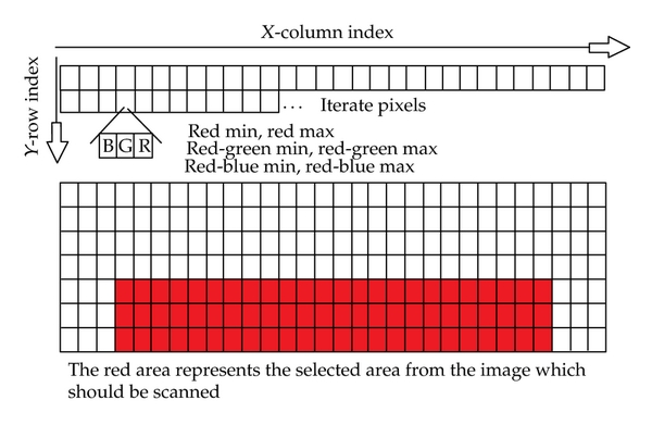
To avoid converting RGB to other colour spaces such as HSV, C. Lin, C. H. Su, H. S. Huang, and K. C. Fan in their journal devised a method which uses 5 constant threshold variables to determine whether an RGB pixel is within a specific colour zone. Assuming the following variable values:
red = Red value of the pixel
green = Green value of the pixel
blue = Blue value of the pixel
minRed = Minimum red threshold value (0–255)
maxRed = Minimum red threshold value (0–255)
minRedGreenRange = Minimum red-green component value (0–255)
maxRedGreenRange = Maximum red-green component value (0–255)
minRedBlueRange = Minimum red-blue component value (0–255)
maxRedBlueRange = Maximum red-blue component value (0–255)
The algorithm considers a pixel to be within a certain colour range if
* minRed < red < maxRed
* minRedGreenRange < red-green < maxRedGreenRange
* minRedBlueRange < red-blue < maxRedBlueRange
Code Snippet: Calculating the thresholds for image segmentation
1
2
3
4
5
6
7
8
9
10
11
12
13
14
15
16
17
18
19
20
21
22
23
24
25
26
27
28
29
for i in range(100,height):
for j in range(70,width-70):
blue = frame[i,j,0]
green = frame[i,j,1]
red = frame[i,j,2]
if blue==0 and red==0 and green==0:
continue
if red < minRed:
minRed = red
if red > maxRed:
maxRed = red
redGreenRange = int(red)-int(green)
redBlueRange = int(red)-int(blue)
if redGreenRange < minRedGreenRange:
minRedGreenRange = redGreenRange
if redGreenRange > maxRedGreenRange:
maxRedGreenRange = redGreenRange
if redBlueRange < minRedBlueRange:
minRedBlueRange = redBlueRange
if redBlueRange > maxRedBlueRange:
maxRedBlueRange = redBlueRange
Code Snippet: Applying the thresholds to image
1
2
3
4
5
6
7
8
9
10
11
12
13
for i in range(height):
for j in range(width):
blue = frame[i,j,0]
green = frame[i,j,1]
red = frame[i,j,2]
redGreen = int(red)-int(green)
redBlue = int(red)-int(blue)
if red > minRed and red < maxRed and redGreen > minRedGreenRange and redGreen < maxRedGreenRange and redBlue > minRedBlueRange and redBlue < maxRedBlueRange:
opImage[i,j] = 255
else:
opImage[i,j] = 0
- Edge Detection
Colour segmentation alone is not enough to fully segment an image, as areas of a similar colour to the floor plane were misinterpreted as traversable space. Thus Canny edge detector isused to generate an edge map and then probabilistic Hough transform is applied to the output. The principle of this procedure is to scan through each pixel in a binary image finding all lines that could fit through this point. If a line fits through enough points then it is considered significant enough to keep. Each point is picked randomly and once enough points have been passed through by a line, then they are removed from any subsequent scanning. This is then repeated until all points are eliminated or there are not enough points left to identify a significant line.
Thus at the end of above procedure we have an edge map consisting of significant edges. In the last step, a polygon is drawn from the start and endpoints of each lines we got in earlier step on top of the colour segmentation map.
Code Snippet: Edge Detection
1
2
3
4
5
6
7
8
9
10
11
12
13
14
15
16
17
18
19
20
gray = cv2.cvtColor(frame, cv2.COLOR_BGR2GRAY)
edges = cv2.Canny(gray, 50, 150, apertureSize=3)
lines = cv2.HoughLinesP(edges, 1, np.pi/180, minLineLength, maxLineGap)
if lines != None:
for i in range(len(lines[0])):
points=[0 for j in range(4)]
if lines[0,i,0] < lines[0,i,2]:
points[0] = (lines[0,i,0],0)
points[1] = (lines[0,i,2],0)
points[2] = (lines[0,i,2],lines[0,i,3])
points[3] = (lines[0,i,0],lines[0,i,1])
else:
points[0] = (lines[0,i,2],0)
points[1] = (lines[0,i,0],0)
points[2] = (lines[0,i,0],lines[0,i,1])
points[3] = (lines[0,i,2],lines[0,i,3])
polyPoints = np.array([tuple(i) for i in points],np.int32)
cv2.fillConvexPoly(opImage, polyPoints, [0,0,0])
Machine Learning
The first step in this section is to prepare data for training. The easiest way to collect data would be to mount camera on top of the bot and use Xbee module as a remote control to navigate bot and collect image samples. Simultaneously, save the direction of movement of robot per frame. In my case I stored the key pressed to control the navigation of robot in a text file. Now, we have training data as well as labels required for training an algorithm.
I used an Artificial Neural Network to control the navigation. I implemented a Neural Network myself and it was my first ML project, so it was not a very optimized version. To see my implementation, please use the link given below. I advice to go through Andrej Karpathy’s blog on ANN’s if you want to implement your own algorithm or you can use Scikit-Learn which is an excellent opensource machine learning library.
Refer my Repository for complete code.
Here is the robot in action
Thanks!