
Line Follower using AVR ATmega32
02 Nov 2015In the last post we discussed about how to build a line follower without using a microcontroller. These kind of line follower robots have certain limitations that they can’t move in reverse direction and don’t employ any feedback mechanism. Also situations when there is a fork or sharp turns in the path, these kinds of robots would fail. The addition of a microcontroller gives us the ability to program our robot according to different situations. Some of the advantages of a microcontroller based line follower are given below:
- More than two sensors can be used to improve the detection or sensing range.
- PWM can be implemented easily without any extra circuitory.
- If correctly programmed, bot can easily take right or acute turns.
So let’s go ahead and look at the materials required to build this robot.
- AVR ATmega32 microcontroller(1)
- AVR USB programmer(1)
- IR Sensors(8)
- 16x2 LCD(1)
- LM324 Operational Amplifier IC(2)
- L293D Motor Driver IC(1)
- 7805 Voltage Regulator IC(1)
- DC Motors(2)
- PCB
- 6V Dynamite battery(1)
- Chassis cut of plywood
- Soldering iron with soldering wire and flux
- Wheels(2)
- Caster Wheel(1)
- L clamp(2)
- Resistors: 330(10), 10k(10)
- Variable Resistors: 10k(8)
- Capacitors: 0.33uF(1), 0.1uF(1)
- Wires and Connectors
- Wire Stripper
Again, we will take the same approach as the previous post and we will divide the project into various subtasks and implement them one by one.
The Sensor array
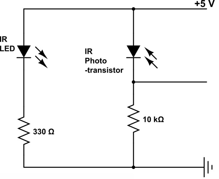
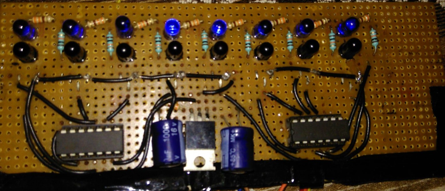
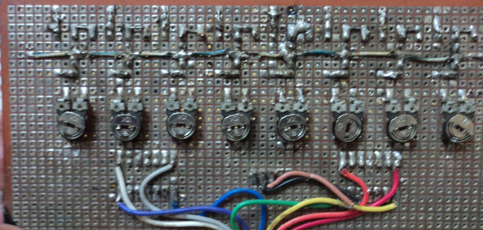
The sensor array has a total of eight sensor pairs. The reason for using more number of sensors is to make the robot more flexible to different problem statements or situations. If there are some constraints regarding the number of sensors, then the sensor array can be implemented using five sensors. The spacing between sensors should be according to arena, in my case it is 2cm. I have connected two LM324 ICs at the bottom of sensor board itself for ADC conversion of signal from the sensor array. You can also use built-in ADC in microcontroller to avoid the extra circuitory. I have soldered potentiometers on the reverse side of sensor board for easy calibration.
Development Board
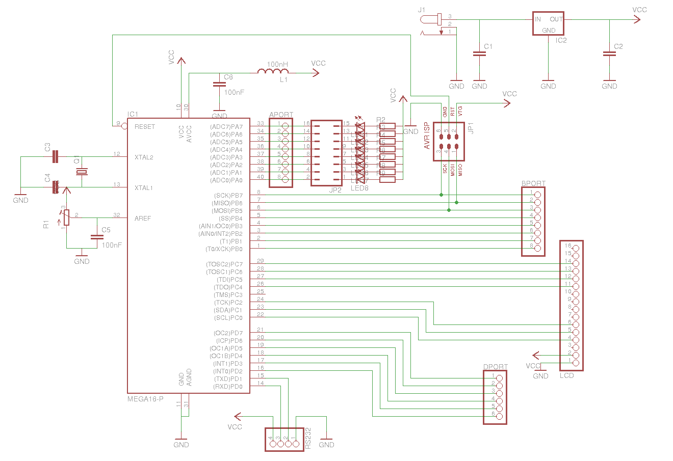
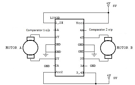
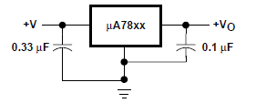
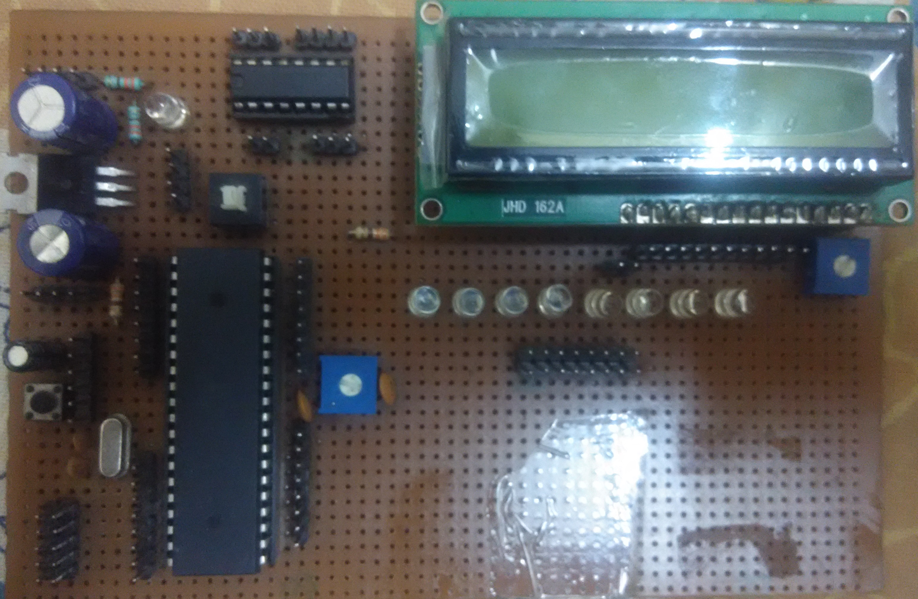
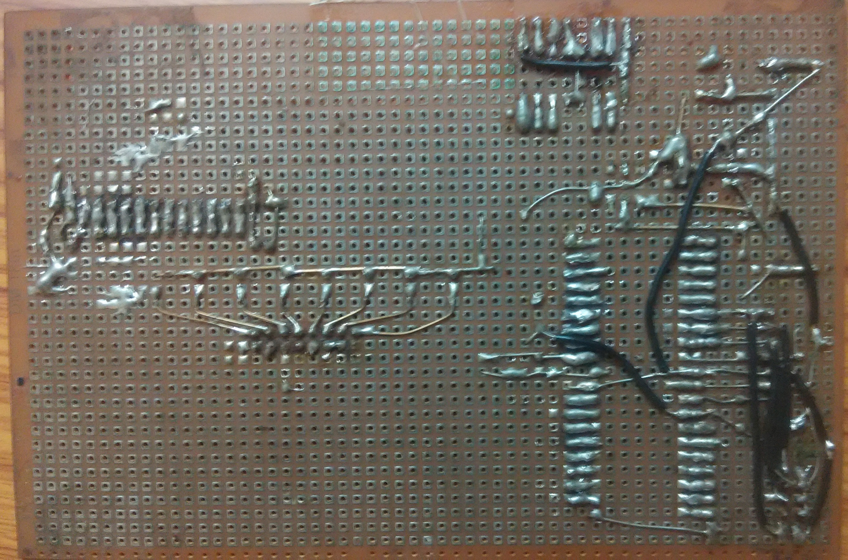
Instead of wiring the microcontroller solely for the purpose of line follower, we will make a multi-purpose development board. As shown in the image I have soldered microcontroller, voltage regulator circuit using LM324, motor driver circuit using L293D, a 16x2 LCD and 8 LEDs(for testing) on a single board. Referring to the pin diagram in the datasheet of Atmega32, the connections to be made are given below:
- Pins 33 to 40 - Sensor array
- Pins 18 to 21 - Motor control pins
- Pins 1 to 3 - LCD Control Pins (RS, R/W and Enable)
- Pins 14 to 17 - LCD Data pins (DB4 to DB7)
- Pins 6 to 11 - ISP header
Algorithm
The sensor readings are taken from the output of LM324 and stored in a byte. If a bit is 1 then the corresponding sensor is on the line and in case of 0 sensor is not on the line.
Sensor Configuration
- Forward - 00011000
- Left - 00110000 or 01100000 or 11000000
- Sharp Left - 10000000
- 90 degree Left - 11110000 or 11111000
- Acute Left - 10011000 or 11001100 or 11011000
- Right - 00001100 or 00000110 or 00000011
- Sharp Right - 00000001
- 90 degree Right - 00001111 or 00011111
- Acute Right - 00011001 or 00110011 or 00011011
- No line - 00000000
Note: In case of any discontinuities, the robot will move straight until it detects the line.
Motor library commands
- init_motors() - This function sets the pins in microcontroller to switch on the PWM functionality which is used to control the speed of motors. It must be called once before the infinite loop.
- set_motors() - This function sets the speed and direction of rotation of motors. Speed can be set between +250 to -250 where +250 signifies full speed in forward direction and -250 signifies full speed in reverse direction.
Code Snippet
1
2
3
4
5
6
7
8
9
10
11
12
13
14
15
16
17
18
19
20
21
22
23
24
25
26
27
28
29
30
31
32
33
34
35
36
37
38
39
40
41
42
43
44
45
46
47
48
49
50
51
52
53
54
55
56
57
58
59
60
61
62
63
64
65
66
67
68
69
70
71
72
73
//straight
if((sensors == 0b11100111)||(sensors == 0b11101111)||(sensors == 0b11110111))
{
set_motors(MAXSPEED,MAXSPEED);
}
//right drift
else if((sensors == 0b11110011)||(sensors == 0b11100011))
{
set_motors((0.5*MAXSPEED),MAXSPEED);
}
else if((sensors == 0b11111001)||(sensors == 0b11110001))
{
set_motors(0,MAXSPEED);
}
else if((sensors == 0b11111100)||(sensors == 0b11111110))
{
set_motors(-(0.5*MAXSPEED),MAXSPEED);
}
else if(sensors == 0b11111000)
{
set_motors(-(0.25*MAXSPEED),MAXSPEED);
}
//left drift
else if((sensors == 0b11001111)||(sensors == 0b11000111))
{
set_motors(MAXSPEED,(0.5 * MAXSPEED));
}
else if((sensors == 0b10011111)||(sensors == 0b10001111))
{
set_motors(MAXSPEED,0);
}
else if((sensors == 0b00111111)||(sensors == 0b01111111))
{
set_motors(MAXSPEED,-(0.5*MAXSPEED));
}
else if(sensors == 0b00011111)
{
set_motors(MAXSPEED,-(0.25*MAXSPEED));
}
//right angle turns
else if((sensors == 0b11100000)||(sensors == 0b11110000))
{
set_motors(ROTATESPEED,-ROTATESPEED);
}
else if((sensors == 0b00000111)||(sensors == 0b00001111))
{
set_motors(-ROTATESPEED,ROTATESPEED);
}
//acute turns
else if((sensors == 0b01100111)||(sensors == 0b00100111)||(sensors == 0b00110011))
{
set_motors(-ROTATESPEED,ROTATESPEED);
}
else if((sensors == 0b11100110)||(sensors == 0b11100100)||(sensors == 0b11001100))
{
set_motors(ROTATESPEED,-ROTATESPEED);
}
//no path
else if((sensors == 0b11111111) && line_break ==0)
{
set_motors(MAXSPEED,MAXSPEED);
_delay_ms(750);
line_break=1;
continue;
}
else if((sensors == 0b11111111) && line_break ==1)
{
set_motors(ROTATESPEED,-ROTATESPEED);
}
else
{
set_motors(ROTATESPEED,-ROTATESPEED);
}
Refer my Repository for complete code.
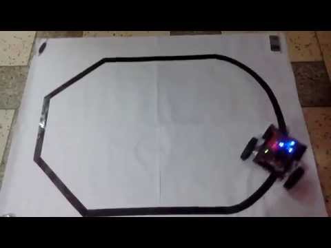
Here is the robot in action
Thanks!