Line Follower Without Microcontroller
26 Oct 2015This is where it all started. I built it around two years ago when I just started experimenting with electronics and programming. It was a fun project which taught me a ton and is a great choice for the beginners in Robotics.
A line follower is an autonomous robot which follows either black line in white area or white line in black area. It could be implemented in several ways. The one that I made is the simplest of all. The robot navigation is controlled entirely by sensors and non-programmable ICs.
Following are the components required to build this line follower
- IR sensors(2)
- Resistors: 220(2), 1K(2), 15K(1), 33K(1), 47K(2), and 100K(1)
- Variable Resistors: 100K(2)
- Capacitors: 47uF/16v(1), 0.33uF(1), 0.1uF(6)
- LM324 Operational Amplifier IC(1)
- L293D Motor Driver IC(1)
- 7805 Voltage Regulator IC(1)
- DC Motors(2)
- PCB
- 6V Dynamite battery(1)
- Chassis cut of plywood
- Soldering iron with soldering wire and flux
- Wheels(2)
- Caster Wheel(1)
- L clamp(2)
We will divide the robot in different building blocks, build them piece by piece and then tie them up together.
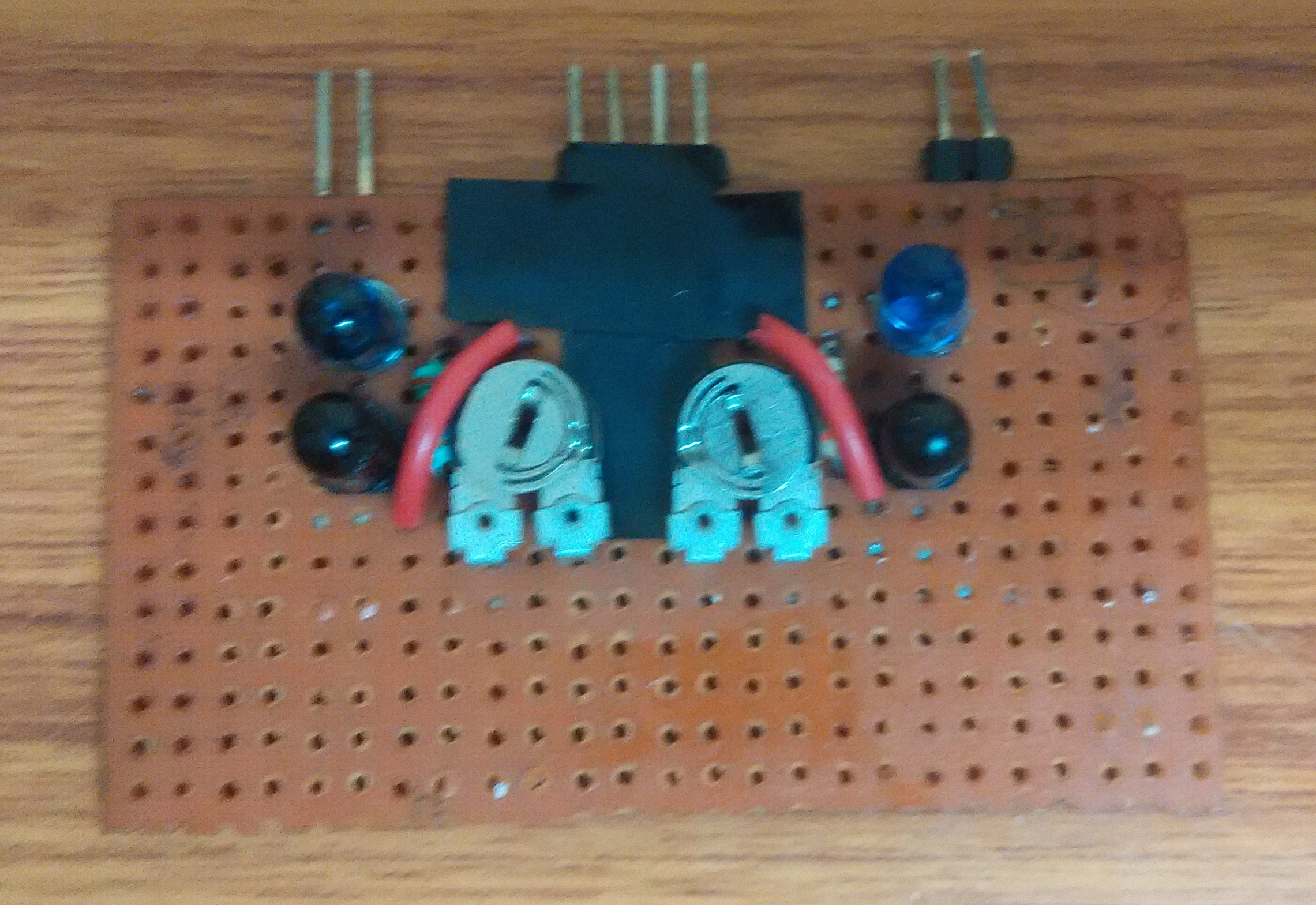
##Sensor Board
An IR sensor is basically a device which consists of a pair of IR LED and photodiode. The IR LED emits IR radiation and the output of the sensor is dictated by the intensity of reception of the radiation by the photodiode. This is a part of the Robot which would actually interact and take input from the surroundings. Use the following schematic for implementation:
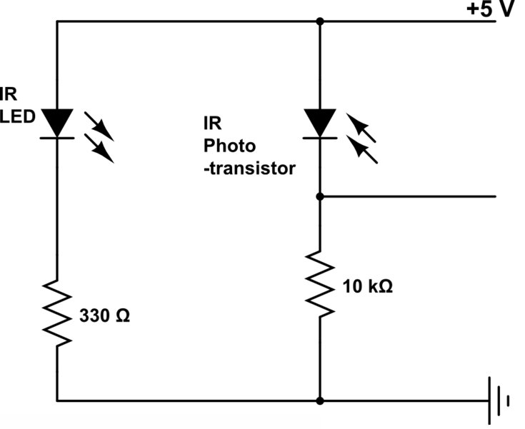
This is the part of the robot which actually differentiates between white and black line. The IR LED emits IR radiation, which in normal state gets reflected back to the module from the white surface around the black line, which gets incident on the photodiode. But, as soon as the IR radiation falls on the black line, the IR radiation gets absorbed completely by the black color, and hence there is no reflection of the IR radiation going back to the sensor module.
Alternatively LDR sensors can also be used instead of IR sensors.
Tip: Since IR LED emits light in the frequency range of Infra-Red, it isn’t visible to the Human eye. Just to make sure that the circuit is correctly soldered, power up the board and observe the LEDs on your cell phone screen using the camera. If they are working correctly you will see them glow.
##The Brain
Till now we have successfully taken input from the arena using IR sensors. But what these sensors really provide is an analog output. To process the output from sensor module and provide input to the motors we will use LM324, a quad comparator IC to convert analog signal from sensor board to a digital signal. Now the use of quad comparators will be discussed a little later. Since we are not using microcontroller in our bot, this IC will serve as a (not so smart) brain. It will simply pick input signal from sensor module, binarize the signal and retransmit it to the motors via motor driver circuit and control its motion as explained below.
If the IR LED emissions become incident on the photodiode, the photodiode’s resistance comes down to a finite value. The drop across the 10K series resistor is what we use as the input, which is compared with the threshold. The point to be noted here is that more the incident radiation on the photodiode, less will be the drop across it, and hence more will be the drop across the series resistor. If the voltage developed across the resistor is greater than the threshold set by us, the output of the IC will be high, else it will be low. Hence, if our reflected radiation is never strong enough to be greater than the threshold and we have a constant low as output, we can reduce the threshold voltage by turning the “minus shaped” slit in the variable resistance towards its terminal where we connected Gnd. In case our threshold is very low and the output is always high in spite of no radiation or if it is just too sensitive, then you can increase the threshold by turning the slit the other way. When the emissions are absorbed by a black surface, the resistance of the photodiode becomes very high due to no incidence of IR emissions on it, and the output remains low.
The output of the comparator IC is connected to one end of motor and the other end is grounded. When the output from IC is high, motor will rotate and if the output is low, motor would stop. So, if the output of both the motors are high(both the sensors on white surface), bot will move forward. If the output of comparator corresponding to left sensor is low and right sensor is high, bot will rotate towards left trying to move left sensor away from the black line and vice versa. Note that the distance between both sensors are to be set a little greater than the width of the line. Otherwise it will move erraticaly or simply won’t move at all. Also, note that there are many other limitations to this implementation like this bot won’t be able to move in the reverse direction.
Tip: Reversing the comparator connections can make bot navigate in arena having white line on a black surface.
##Pulse width Modulation
Till now we were using constant voltage supply for the threshold voltage. Imagine if we could use triangular waves as threshold, than the varying voltage on the other pin of compartor would produce square waves of varying duty cycle i.e. Pulse width modulated waves. This wave can be further used in controlling speed of the motors. I won’t go in much details as there is an exceptional explanation of this here.
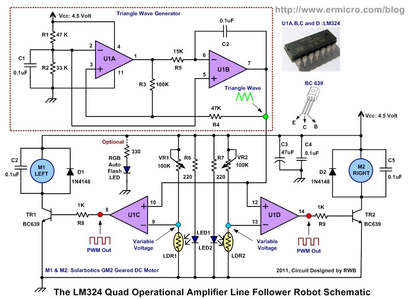
The above picture has been taken from here. I have not exactly followed the above circuit. They have used LDR sensors in place of IR sensors, transistors to drive motor and some other minor changes which can be easily figured out.
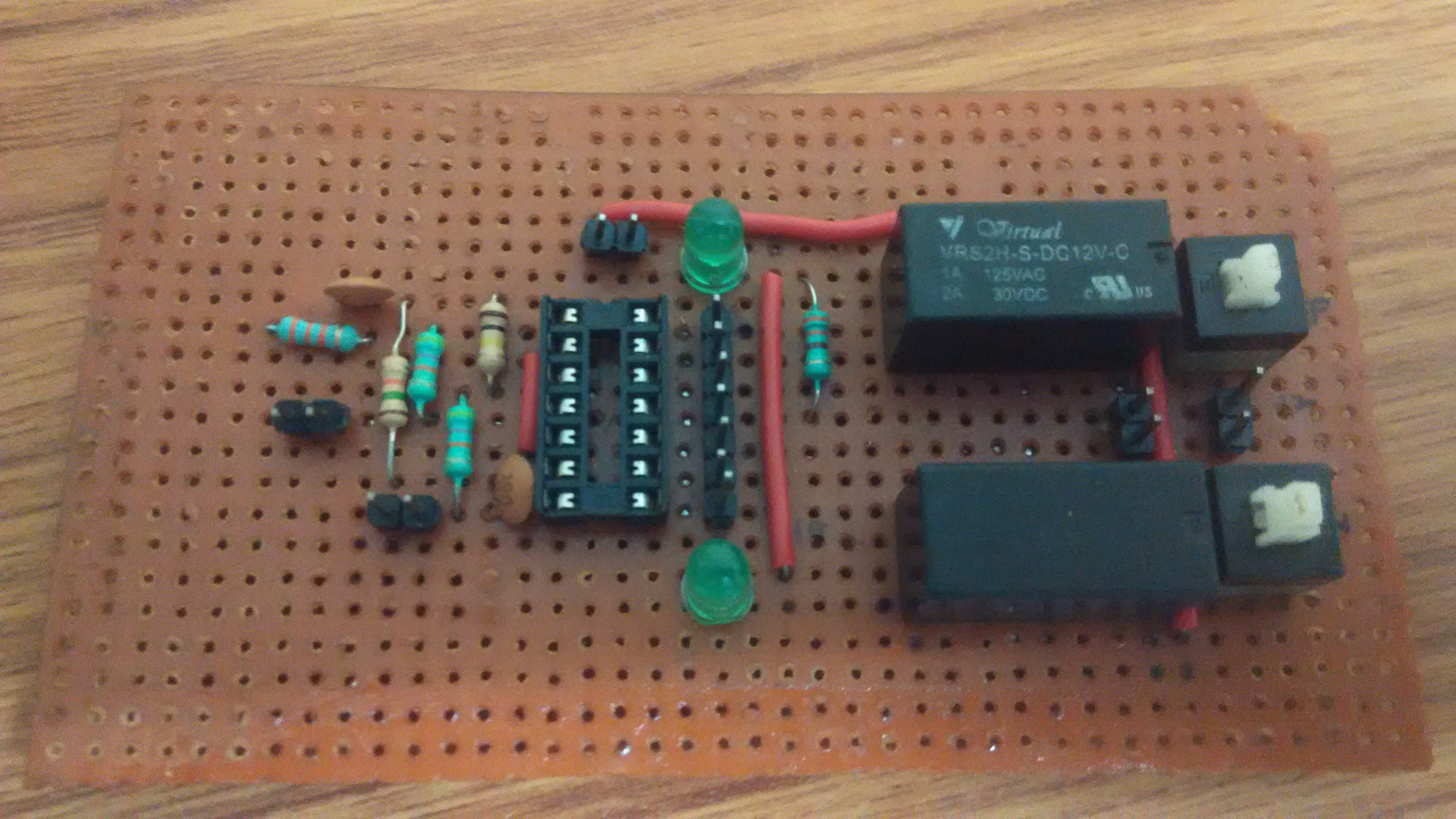
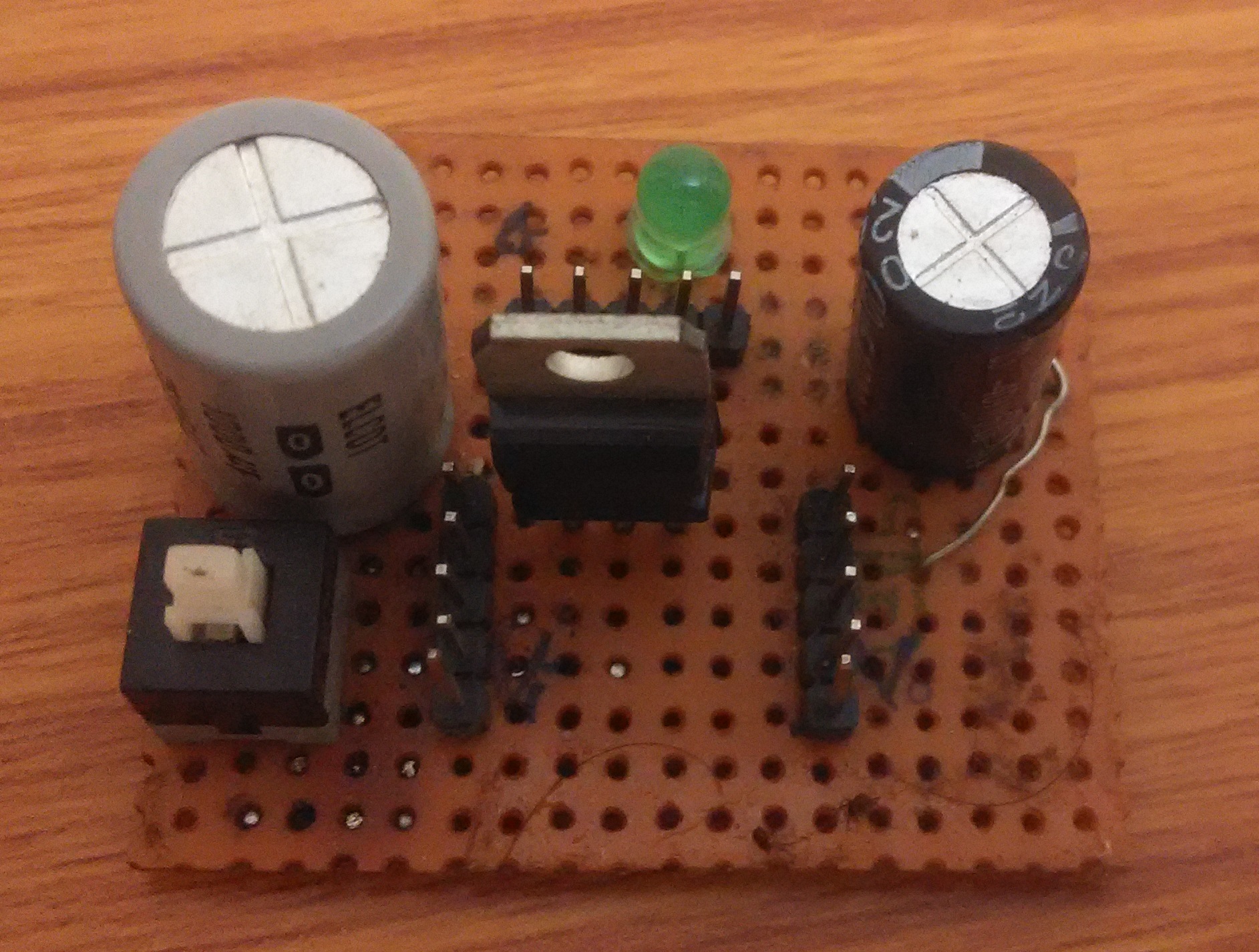
Below is my implementation of this circuit.
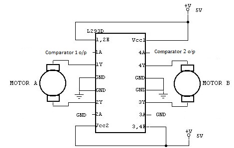
##Motor Driver Circuit
This is a very easy circuit. Just follow the above circuit diagram and you will be ready to go.
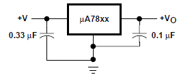
##Power Supply
If a power supply of greater than 5v is used in the circuit, than a voltage regulator must be used to trim the voltage. Also it is advised to use a seperate power supply for motor driver circuit. Solder a 0.33uF capacitor to the input pin of IC and a 0.1uF capacitor to the output pin and connect the othe end of capacitors to a common ground. Also connect the middle pin to the common ground. I have also connected an LED through 330ohm resistor for the on/off notification.
##Chassis
Well the difficult part is over. The only thing left is to get a chassis and assemble all the above parts. I made chassis by cutting out a small piece from plywood. Motors can be attached to chassis using L clamps. Also prebuilt chassis can be used. Now all that is left is combining all the parts and giving your bot a run.
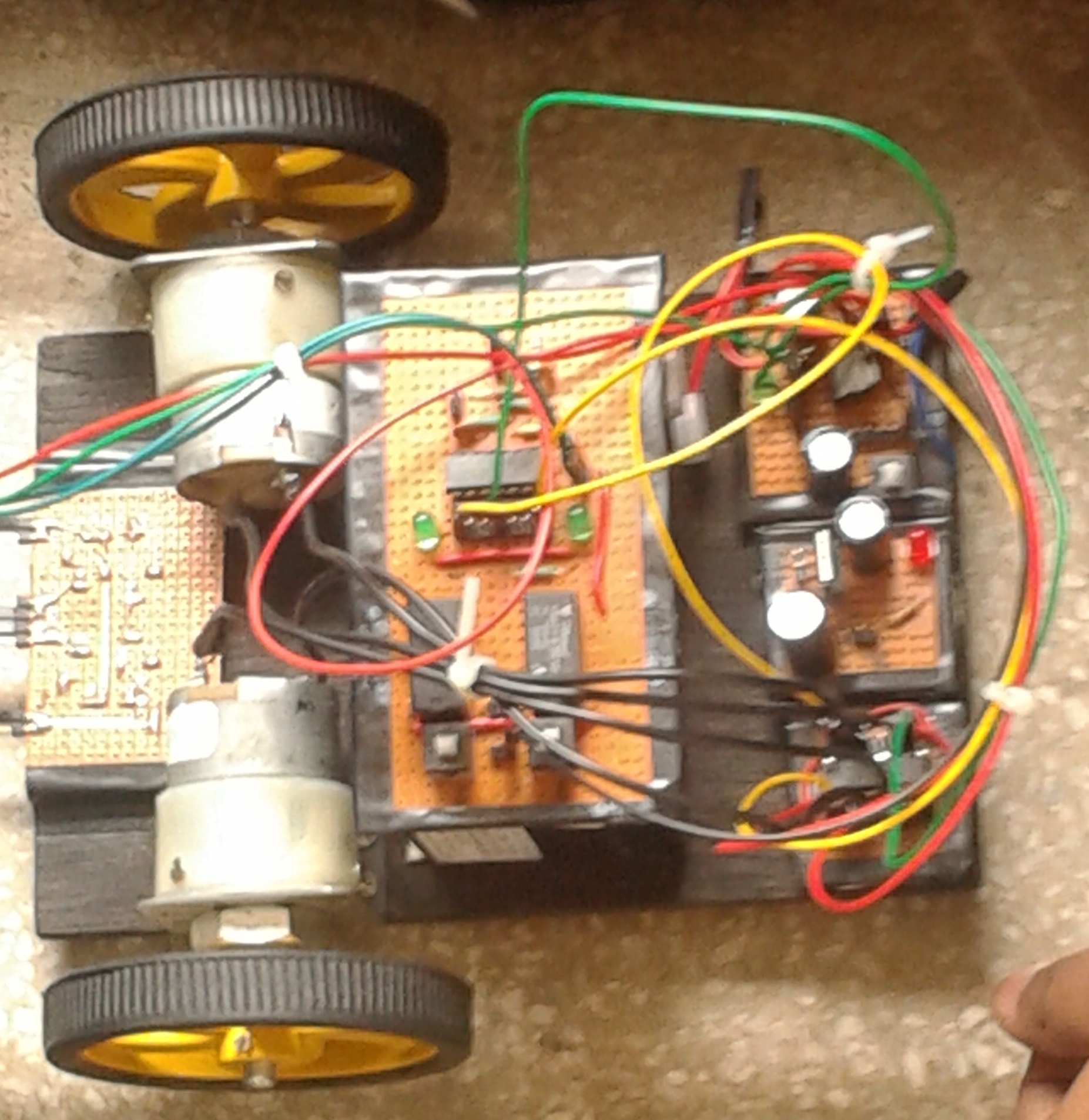
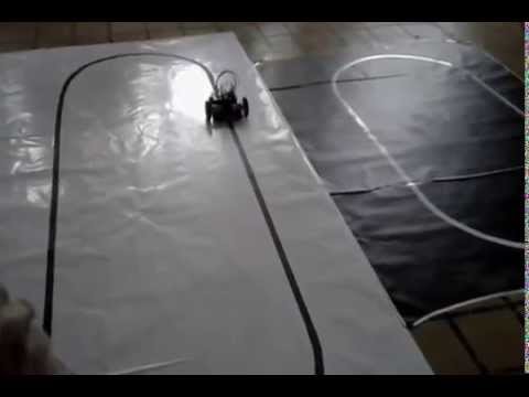
Below I have attached the picture of the final implementation. Also I want to mention that this bot won first place in IIT Delhi’s techfest Tryst’14. I have also attached the video which my team took during the performance at IIT Delhi.
Thanks!